

-

Founded in 1996, we provide integrated "Industry 4.0" software and equipment solutions for manufacturing enterprises. We are committed to the R&D and manufacturing of intelligent, green, and user-friendly intelligent equipment, continuously promoting the deep integration of information technology and industrialization. -
-
Auxiliary material feeding system for rubber tires/rubber products
-
Automatic Batching System for Cables and Cable Polymer Materials
-
Centralized feeding system + automatic batching system for plastic polymer materials
-
Automatic batching and full-process control system for friction materials
-
Green and environmentally friendly equipment and online environmental monitoring system
Product
Serving global clients in industries such as friction materials, building materials, rigid foam boards, welding materials, magnetic materials, and lithium batteries, we provide intelligent and environmentally friendly automated batching systems (auxiliary equipment for internal mixers/kneaders, automatic batching systems for small materials/additives, automatic batching systems for polymer materials, and automatic batching systems for composite materials). -
-
Tailored solutions: We provide suitable technical solutions and personalized services throughout the process, based on each client's needs and circumstances, and we pay attention to clients' potential needs. -
Following the principles of "intelligent control, advanced technology, practical stability, simple operation, and convenient maintenance", with a "professional" spirit and a "focused" attitude, we closely combine the user's actual production and development goals. Through continuous innovation and improvement, we effectively solve the production and management problems that users care most about, achieving "user satisfaction, joint innovation, and common development". -
Through company-wide innovation and continuous improvement, we constantly enhance product cost-effectiveness and stability. We continuously increase R&D investment to improve technological advancement and capabilities. Through continuous improvement of service models, we enhance service quality. We firmly follow the path of "specialization" to become a global professional company.
Walk - Take you to explore what is unusual about the Mach auxiliary machine 2 - Pneumatic conveying system
Published Time:
2022-04-08
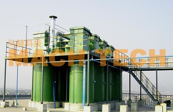
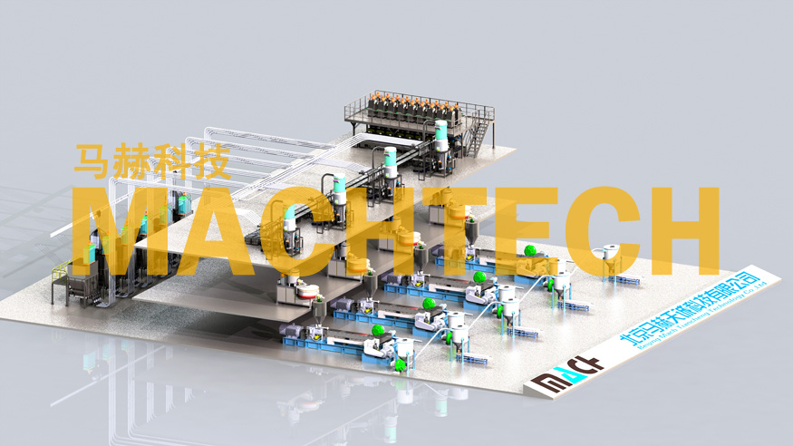
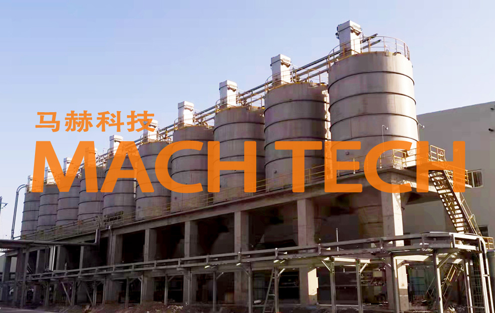
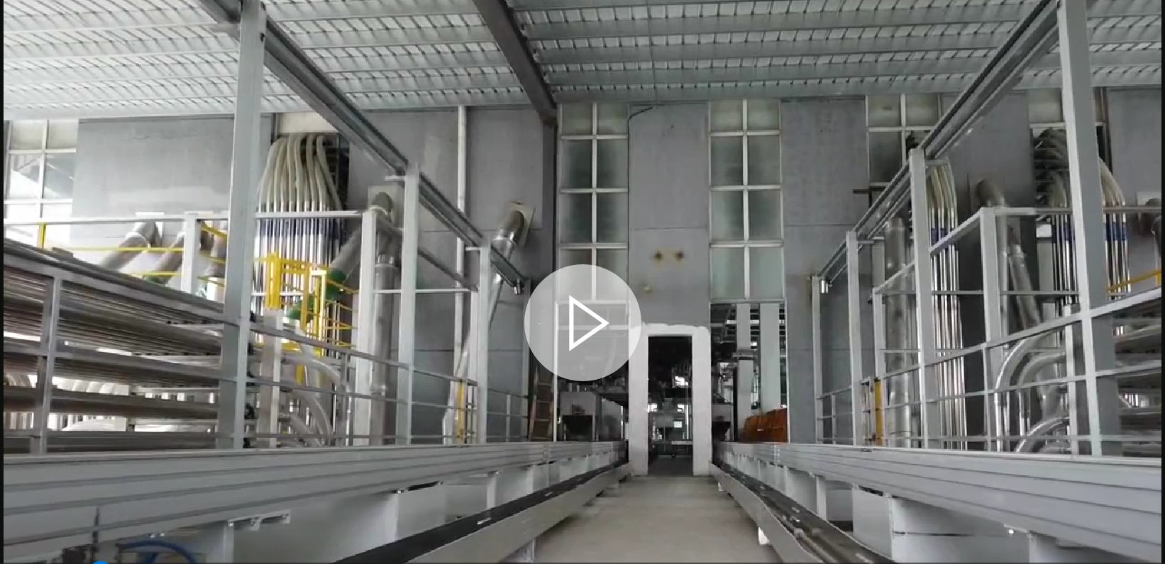
Large factories in the rubber, plastics, chemical, food and pharmaceutical industries, due to their high production capacity and large raw material consumption, rely heavily on Maher pneumatic conveying in their raw material handling processes. Firstly, the pneumatic conveying system receives large raw materials (such as carbon black, granules, and zinc oxide) upon arrival at the factory and feeds them into storage silos. These materials are then transferred according to a schedule to the storage tanks of Maher auxiliary equipment/automatic batching systems in the production workshop.
Large factories in the rubber, plastics, chemical, food and pharmaceutical industries, due to their high production capacity and large raw material consumption, rely on Maher pneumatic conveying systems for raw material handling. The system first receives large raw materials (such as carbon black, granules, and zinc oxide) upon arrival, transferring them to storage silos before planned delivery to production workshops. Auxiliary equipment /Automatic batching storage tanks.
Maher pneumatic conveying systems utilize airflow transportation (including negative pressure and positive pressure pneumatic conveying) and mechanical transportation. With 20 years of experience and technological advancements, the system has overcome long-standing industry challenges such as pipeline blockages, high breakage rates, material accumulation, residue, and operational instability, attracting customers from various industries.
I. Conveying Methods
In gas pipeline systems, airflow movement can be categorized into three types: ① Vacuum pneumatic conveying, using negative air pressure in the pipeline to transport materials; ② Air-fluidized conveying, using compressed air in the pipeline to transport materials; ③ Mixed conveying, establishing a vacuum in one section of the pipeline and introducing compressed air into another section for continuous material transport, also known as circulating conveying.
The conveying capacity and distance of vacuum pneumatic conveying are related to the vacuum degree. Normal operation is possible for distances under 50m and capacities less than 5t/h.
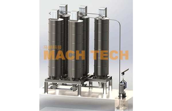
Carbon black positive pressure dense-phase pneumatic conveying, a method developed and refined by Maher over nearly 20 years, achieves transport distances of 300m, capable of supplying materials to multiple workshops and machines. The system primarily consists of an air compressor, feeding device, pressurization tank, conveying pipeline, bypass pipe and bypass air intake pipe, distribution valve, separator (bag filter), and storage tank. The key difference between this system and carbon black negative pressure and carbon black positive pressure dilute-phase pneumatic conveying systems lies in the inclusion of a bypass pipe and bypass air intake pipe in the carbon black conveying pipeline. Compressed air is introduced into the bypass pipe. When blockage is detected in the carbon black conveying pipeline, the compressed air in the bypass pipe enters the conveying pipeline via the bypass air intake pipe, cutting the carbon black into shorter plugs for normal transport. An air booster ensures unidirectional airflow between the carbon black conveying pipeline and the bypass pipe.
II. System Composition
(1) Feeding Device
Powder materials are packaged in three forms: jumbo bags, small bags, and tank trucks. The current device primarily uses manual unpacking and feeding, with two work stations for jumbo bags and small bags respectively. A bag filter is also included to collect carbon black dust from the feeding port, maintaining a clean working environment. After unpacking, the material is sent to an intermediate tank, then automatically fed to the sending tank using a screw feeder.
For convenience and cost reduction, the use of bulk carbon black tank trucks is expanding. These trucks primarily use gravity unloading, with internal compartments for different raw materials and corresponding unloading ports at the bottom. After aligning the truck's unloading port with the feeding port, a lifting cylinder raises and tightens the flange, enabling unloading.
(2) Feeding and Pressurization Device
1) Feeder
A commonly used feeder is the cross feeder, which continuously and uniformly supplies material to the conveying system. The cylinder and discharge plate maintain close contact to prevent air leakage into the hopper. The cross feeder typically operates at 20-60 r/min.
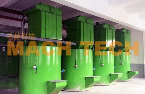
2) Pressurization Device
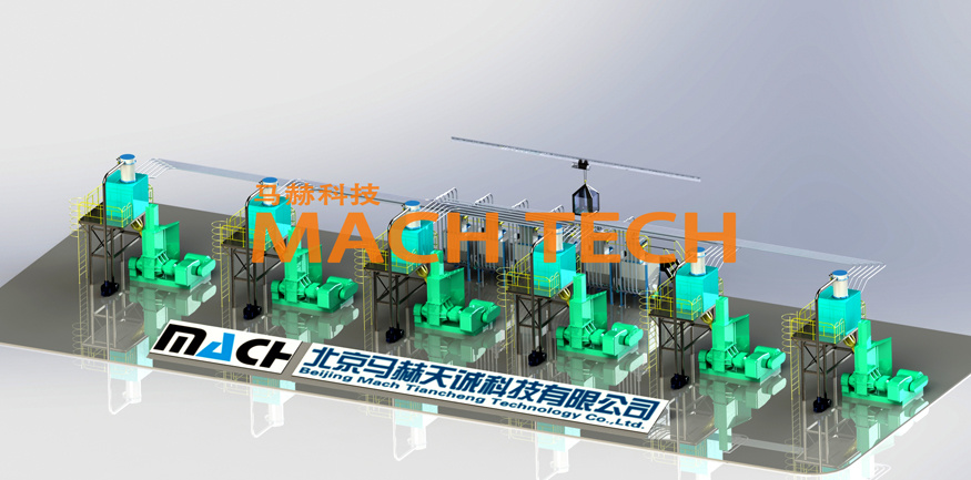
The key component of the pneumatic conveying system is the pressurization device, consisting of a sending tank, pressurization pipeline, control valves, and pressurization tank. Under operating pressure, it must ensure uniform feeding and prevent gas leakage. After entering the sealed sending tank, the carbon black is fluidized before pressurization. The pressurization tank uses compressed air to send the fluidized material into the conveying pipeline.
A work cycle consists of four basic processes: feeding, inflation, pressurization, and cleaning. Continuous conveying is controlled by computer-based detection of tank level changes. To ensure reliable repeated loading and pressurization under stable conveying conditions, a "triple-safety" control method using a level meter, pressure sensor, and timer is employed. The timer serves as a backup in case of level meter or pressure sensor failure.
Pressurization tanks can be single or double. Single tanks operate intermittently; feeding stops during material transport. Double tanks operate in parallel, alternating to achieve continuous feeding. Single-tank systems only allow intermittent transport, with instability at the end of each cycle (dilute-phase suspension conveying), negating the advantages of dense-phase conveying (low speed, high concentration, low carbon black breakage). Double tanks allow alternating transport, enabling continuous conveying. While one tank is loading, the other is feeding, maximizing the advantages of dense-phase pneumatic conveying.
3) Reducer
The outlet of the pressurization tank is connected to the conveying pipeline via a reducer, with compressed air introduced at the pipe end. Conveying pressure depends on material properties, distance, and pipe bends. The pressure is determined based on the relationship between actual pressure and breakage quality.
Reducers consist of gradually narrowing and widening pipes. As the pipe narrows, airflow velocity increases, creating negative pressure at the feeder inlet, drawing material into the pipeline. This also generates sufficient force to overcome downstream resistance. To minimize pressure loss, the central angle α of the converging section should not exceed 60°, and the end should be rounded. The central angle β of the diverging section should not exceed 7°.
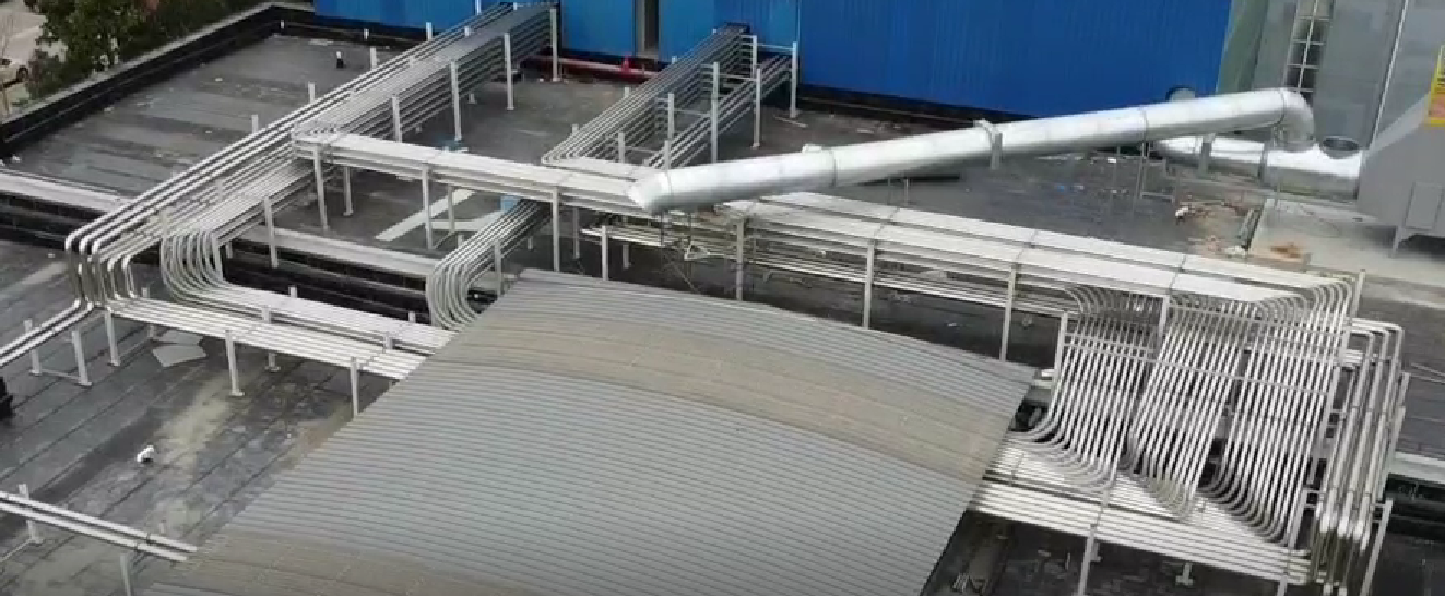
(3) Pipeline System
A dense-phase pneumatic conveying system using a double-pipe design is employed. Carbon black conveying pipelines can be made of stainless steel, aluminum alloy outer pipes with anti-static rubber inner pipes, or ultra-high molecular weight polyethylene pipes. Regardless of the material used, the inner surface must be smooth, anti-static, lightweight, and rust-proof.
The role of the external bypass pipe (companion pipe) is to supplement airflow into the conveying pipe to clear accumulated carbon black. It connects to the carbon black conveying pipe at regular intervals, but the connection is unidirectional, only allowing compressed air from the bypass pipe to enter the carbon black conveying pipe, not vice versa. When the conveying pressure in a certain section of the carbon black conveying pipe rises to a certain value due to carbon black accumulation, the signal detected by the pressure sensor communicates with the PLC, controlling the automatic injection of high-pressure air from the bypass pipe into the rear section of the pressure increase point. The supplementary airflow dilutes and clears the carbon black accumulation until the pressure returns to normal.
The conveying pressure of carbon black is generally around 0.2 MPa. The distance between the two air intake pipes on the bypass pipe is related to the physical properties of the material being conveyed and the conveying distance, generally 5 to 15 times the diameter of the conveying pipe. The gas pressure in the bypass pipe must be higher than the conveying pressure in the conveying pipe. To prevent carbon black from flowing back into the bypass pipe when the airflow in the bypass pipe stops, causing the bypass pipe to fail, a one-way valve and a filter nozzle are installed in the bypass air intake pipe. The cross-sectional area ratio of the bypass pipe to the carbon black conveying pipe is 1:(5-10), with the actual value selected according to the specific situation.
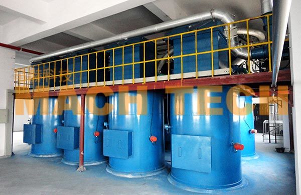
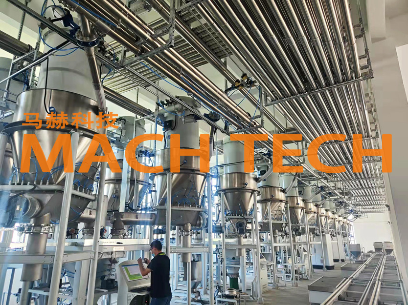
(4) Collection Device
Cyclone separators are used for collecting powder and carbon black. They are relatively inexpensive and easy to install. In discharge-type pipeline systems, bag filters are often used, which have higher collection efficiency, but the bags need to be replaced regularly. The material-gas mixture is separated in the space formed by the conveying pipe end, the storage tank, and the cyclone separator. The carbon black falls into the storage tank, and the gas is purified by the cyclone separator and discharged by the fan. The filter bags are made of waterproof, oil-proof, and anti-static materials. The volume of air to be treated should be calculated based on the characteristics of the material, conveying pressure, conveying speed, and geometric parameters of the conveying pipe, and automatically controlled, using variable frequency speed control to adjust the air volume of the fan.
(5) Distribution Device
After the material is collected, it is usually distributed to Auxiliary equipment various storage hoppers for storage, and then enters the material metering and feeding process.
Tags:
Beijing Mach Tiancheng Technology Co., Ltd.
Address: 12th Floor, Building B, Yu Hui Building, No. 73 Fucheng Road, Haidian District, Beijing
Telephone:86 010-88152355
Fax: 010-88133042
Email:xiayanqiu@machtech.com.cn