

-

Founded in 1996, we provide integrated "Industry 4.0" software and equipment solutions for manufacturing enterprises. We are committed to the R&D and manufacturing of intelligent, green, and user-friendly intelligent equipment, continuously promoting the deep integration of information technology and industrialization. -
-
Auxiliary material feeding system for rubber tires/rubber products
-
Automatic Batching System for Cables and Cable Polymer Materials
-
Centralized feeding system + automatic batching system for plastic polymer materials
-
Automatic batching and full-process control system for friction materials
-
Green and environmentally friendly equipment and online environmental monitoring system
Product
Serving global clients in industries such as friction materials, building materials, rigid foam boards, welding materials, magnetic materials, and lithium batteries, we provide intelligent and environmentally friendly automated batching systems (auxiliary equipment for internal mixers/kneaders, automatic batching systems for small materials/additives, automatic batching systems for polymer materials, and automatic batching systems for composite materials). -
-
Tailored solutions: We provide suitable technical solutions and personalized services throughout the process, based on each client's needs and circumstances, and we pay attention to clients' potential needs. -
Following the principles of "intelligent control, advanced technology, practical stability, simple operation, and convenient maintenance", with a "professional" spirit and a "focused" attitude, we closely combine the user's actual production and development goals. Through continuous innovation and improvement, we effectively solve the production and management problems that users care most about, achieving "user satisfaction, joint innovation, and common development". -
Through company-wide innovation and continuous improvement, we constantly enhance product cost-effectiveness and stability. We continuously increase R&D investment to improve technological advancement and capabilities. Through continuous improvement of service models, we enhance service quality. We firmly follow the path of "specialization" to become a global professional company.
Walk - Take you to explore what unusual things are there in Mach's auxiliary machine 3 - Pink oil glue system
Published Time:
2022-04-15
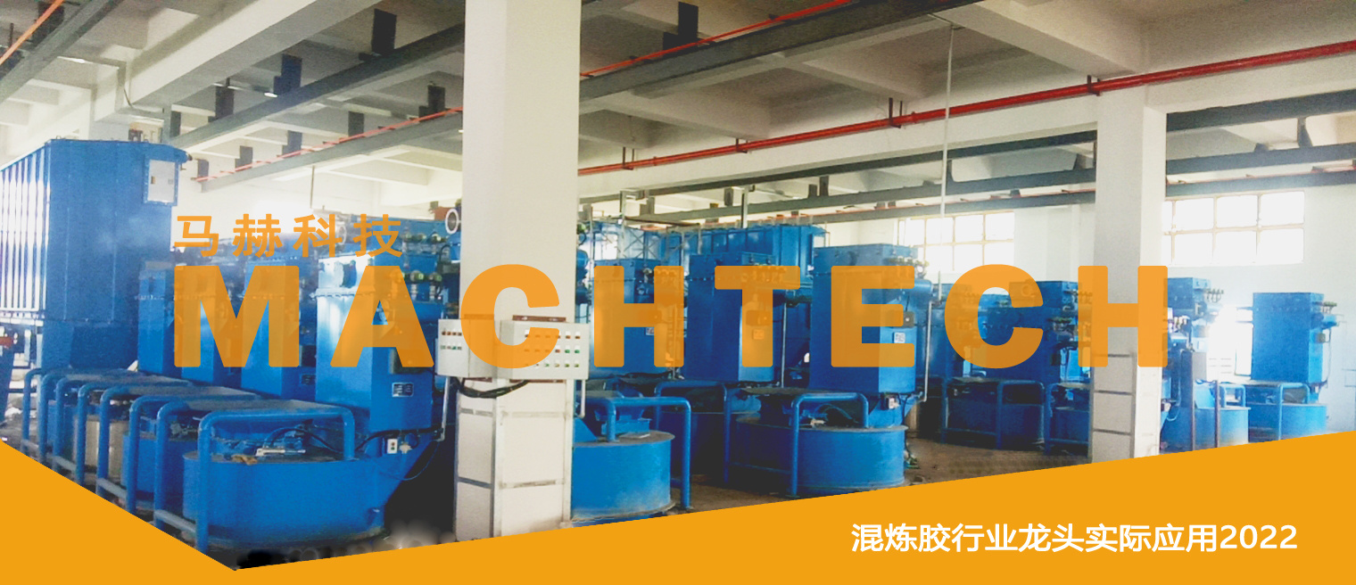
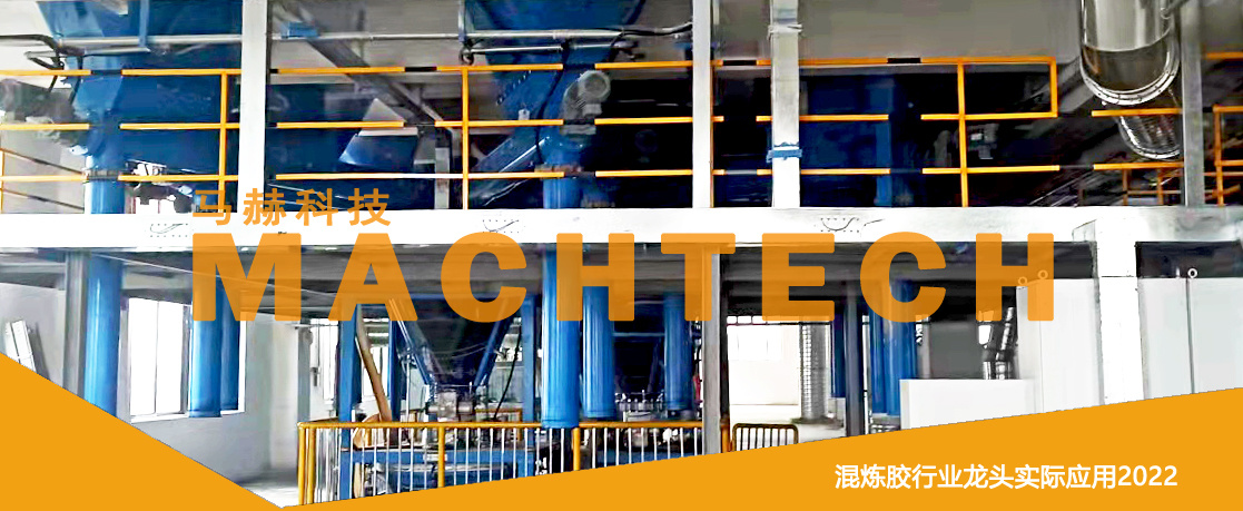
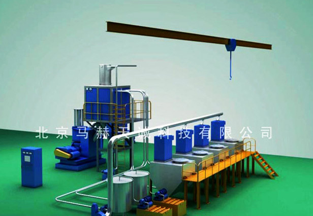
The Mach auxiliary machine system weighs batches of rubber raw materials (powder, oil, and solid forms, referred to as powder-oil-rubber in the industry) according to the formula and then transports them to the mixing chamber.
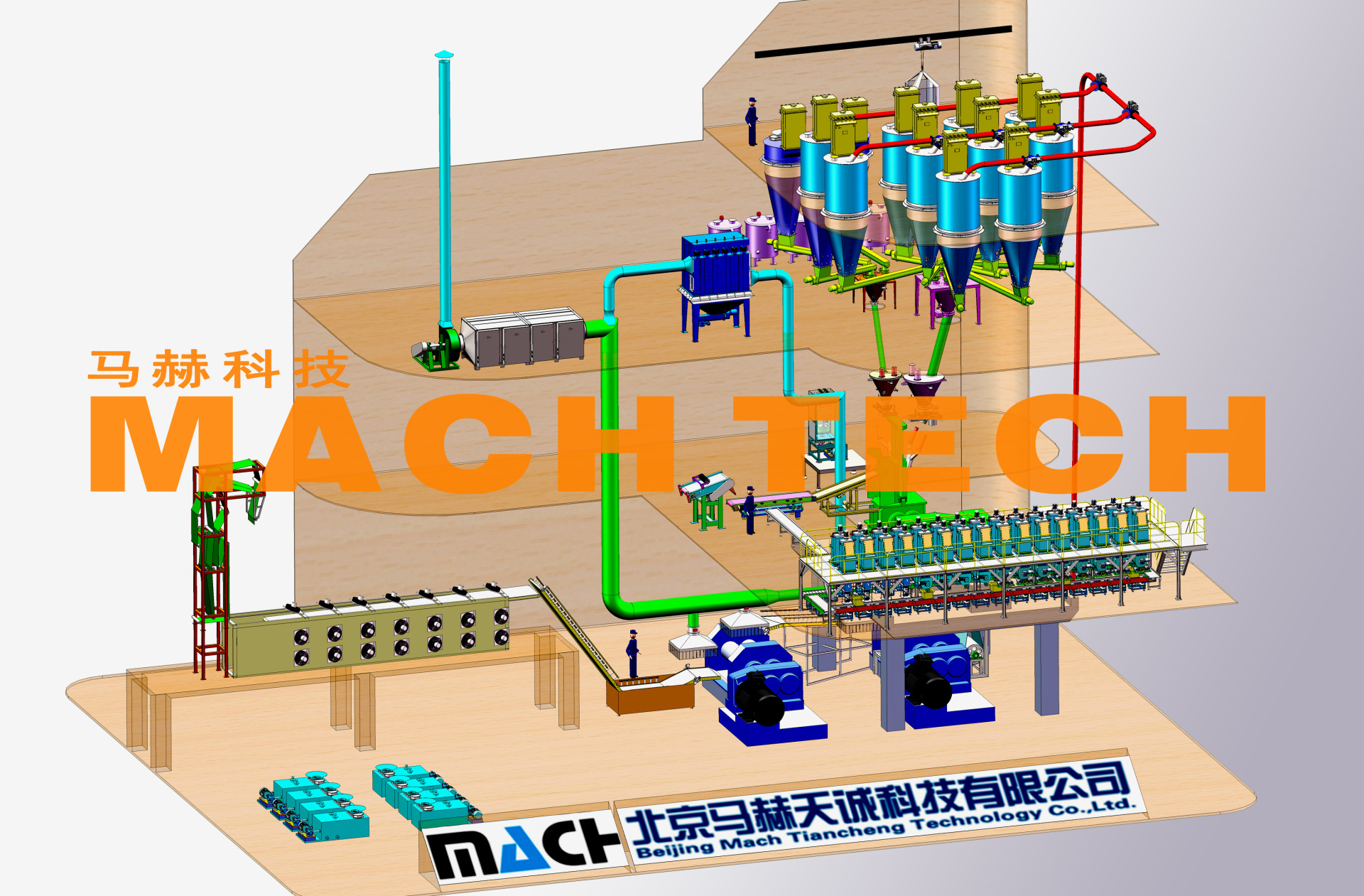
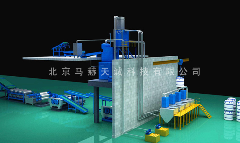
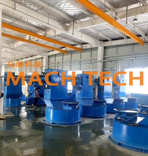
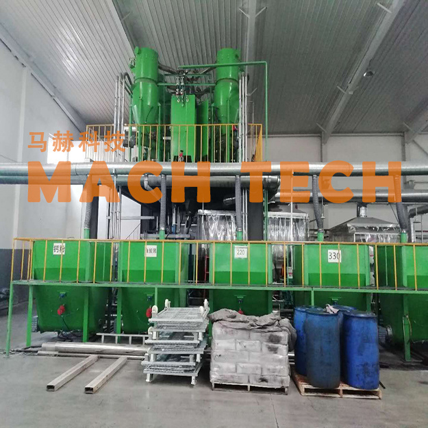
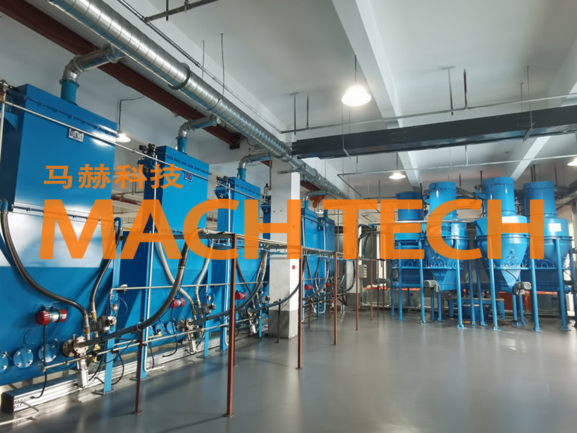
Mach auxiliary equipment systems are customized to different forms based on customer process requirements and plant conditions, including three-dimensional auxiliary equipment (three-to-four-story factory buildings, mostly with drop-type large-capacity internal mixers), negative pressure + three-dimensional auxiliary equipment (one-to-two-story factory buildings, matched with internal mixers or kneaders, with entire line control), negative pressure conveying auxiliary equipment 、 small three-dimensional auxiliary equipment, off-line auxiliary equipment (one or two-story factory buildings, matched with kneaders, with entire line control). The auxiliary equipment weighs the rubber raw materials (powder, oil, and rubber in the industry) in powder, oil, and block forms according to the formula in batches and then conveys them into the mixing chamber.
Auxiliary equipment The material conveying method in the system is: for powdery materials, dry and clean compressed air is used as the conveying medium. The air source must be de-oiled (oil content ≤0.1mg/cm 3 ), dewatered (dew point below -40℃), and filtered and de-dusted (dust particle size <0.1μm), with a pressure not less than 0.7MPa; for oil (liquid), a pressure pump or gravity conveying is used; for block materials (rubber), belt conveying is generally used.
The Mach auxiliary equipment system includes a carbon black storage tank, a screw feeder, a carbon black scale, a rubber sheet guiding machine, a rubber scale, a feeding conveyor belt, an oil scale, and an oil injection device, responsible for the weighing and feeding of formula materials. The dynamic allowable error of all weighing devices in the system is required to be ≤0.2%.
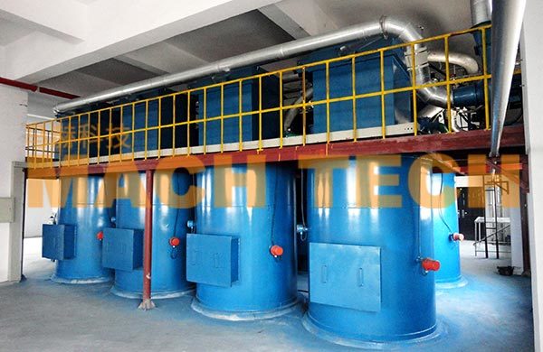
1. Carbon black weighing and feeding system
This system is located above or to the side of the drop-type internal mixer/reversing internal mixer feeding port and consists of a carbon black storage tank, conveying equipment, a carbon black scale, a post-feeding device, and a dust removal device.
( 1) Carbon black storage tank
The number of carbon black hoppers is determined according to the types of carbon black required and is reasonably arranged. The volume of the hopper should be determined according to the amount of a type of carbon black in a batch and the factory building structure. There are two ways to add materials to the carbon black storage tank: one is pneumatic conveying from the factory's carbon black storage silo; the other is unpacking and adding carbon black jumbo bags above the storage tank. The former is closed; the latter is equipped with a dust removal and purification device at the unpacking port. Currently, large rubber processing enterprises mostly use the former, which is beneficial for environmental management; the advantages of using the latter are reducing carbon black particle breakage, saving investment, reducing energy consumption, and reducing maintenance costs.
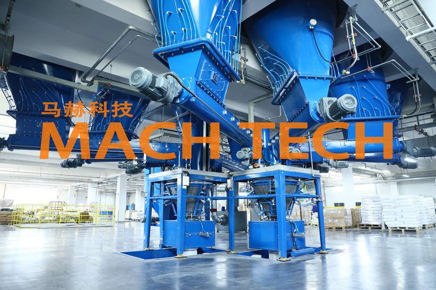
The carbon black hopper is designed according to the standard for normal pressure containers, and the material is carbon steel or stainless steel. If carbon steel is selected, the inner surface should be coated with anti-static paint; if stainless steel is selected, the inner surface should be polished. For different products, different production scales, and different factory building rubber mixing workshops, the volume of the carbon black storage tank ranges from 6 to 30m 3 . The storage tank is equipped with a level meter, and the level information is transmitted to the control system for control.
Due to the large differences in the physical properties of carbon black, such as mechanical properties, fluidity, moisture content, and particle size, arching or "rat holes" are easily formed in the storage tank, increasing the difficulty of discharging carbon black from the storage silo. Arching and "rat holes" are both caused by the flow of viscous materials. Arching occurs in the later stage of discharging from the overall flow hopper, appearing in the upper part of the storage tank and gradually strengthening; "rat holes" occur in the centrally flowing hopper and appear from the beginning. Arching or "rat holes" are also related to the shape and structural dimensions of the storage tank, the wall angle, the size of the discharge port, etc., especially the cross-section of the discharge port section cannot be designed as a symmetrical shape.
Mach uses cylindrical design, arch breaking devices, combined with various stirring devices, and multiple methods using PLC control programs to overcome the technical barrier of arching and bridging.
( 2) Conveying equipment
(1) Screw feeder
The spiral surface of the screw feeder is welded from high-quality steel plates. The inner surface of the screw groove and the spiral surface are coated with anti-adhesive epoxy resin paint. According to the characteristics of the carbon black being conveyed and the actual length of the conveying spiral, it can be designed as an equidistant spiral, an intermittent spiral, or a variable-pitch spiral. For carbon black with high viscosity, a belt spiral conveyor is used to reduce the adhesion surface.
(2) Pneumatic flow trough
The pneumatic flow trough utilizes the potential energy of the material. The carbon black is "fluidized" by compressed air and conveyed under the action of the carbon black's own weight. Compressed air enters the air chamber and enters the material chamber evenly through the filter plate to complete the fluidized conveying of carbon black. The pneumatic flow trough can only convey carbon black from a high place to a low place, and the trough angle is generally 5°~20°.
The pneumatic flow trough has a simple structure, high conveying efficiency, and a wide range of applications. Most commonly used carbon blacks can be conveyed in this way, but white carbon black is not suitable.
The breakage rate of carbon black in the pneumatic flow trough is the smallest among all conveying methods. Its conveying capacity depends on the cross-sectional area of the trough, the inclination angle, the compressed air flow rate, the air pressure, and the material, thickness, and air gap of the filter plate. Filter plates are made of various fibers and plastic microporous plates. The filter plates used for conveying carbon black are generally made of three-proof needle-punched felt (oil-proof, waterproof, and anti-static).
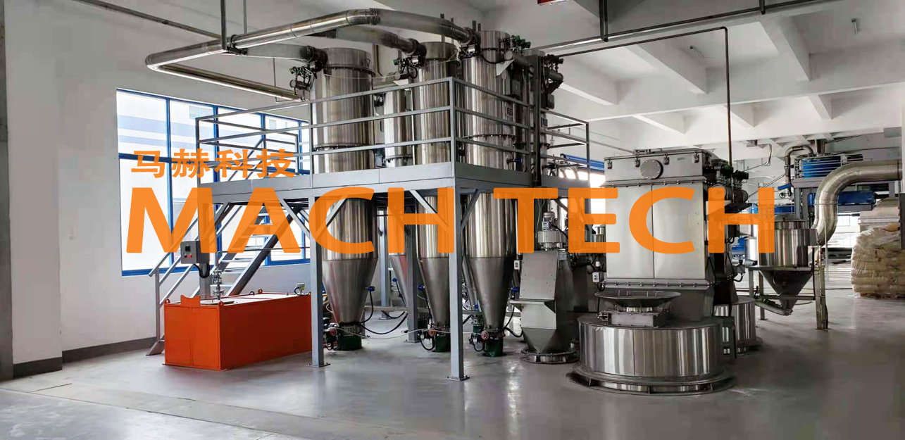
( 3) Carbon black scale
Its function is to cumulatively weigh the carbon black sent by the feeding device and put it into the intermediate hopper.
The carbon black scale consists of a carbon steel weighing hopper, a weighing sensor, and a weighing instrument. Currently, Mach Technology has newly developed a soft scale without a metal shell based on the material characteristics of different customers, which can more effectively solve the problem of incomplete discharge of sticky materials to ensure the quality of the rubber.
Carbon black scales for high-speed, high-capacity internal mixers require a faster weighing speed to complete the weighing of a large amount of carbon black within a limited time.
( 4) Post-feeding device
The function of the post-feeding device is to feed carbon black into the internal mixer. It includes a feed chute, intermediate hopper, level detection, and discharge valve. The feed chute has a rubber-lined bottom, and the material is discharged by vibrating the rubber plate. The discharge valve is used for discharging material in case of abnormal situations.
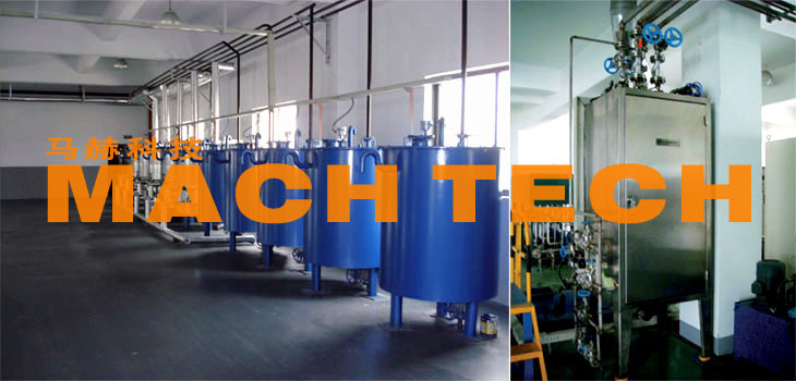
2. Oil delivery, weighing, and injection system
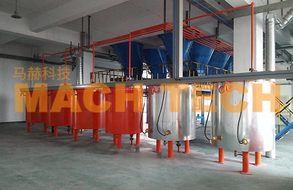
( 1) Oil delivery system
The oil delivery system mainly consists of an oil insulation tank, oil pump, pipelines, and valves. The oil is pumped into the oil insulation tank and transported and fed using the high potential energy of the oil - its own weight. During the conveying and weighing process, the viscosity of the oil is lower at lower temperatures, but the oil cannot flow smoothly in the pipeline. To ensure that the material has a certain temperature, two heating methods are usually used.
(1) Casing method: The oil pipe is encased in a thicker steel pipe, and steam is passed between the two pipes. The casing method provides better heating but is difficult to maintain.
(2) Clamp method: The oil pipe is clamped between three steam pipes, and asbestos is wrapped around the outside.
( 2) Oil scale
Its function is to cumulatively weigh the oil and inject it into the internal mixer. The oil uses electric heating or steam heating, and a temperature sensor and digital display meter control its temperature to adjust the viscosity of the transported oil. Steam heating uses a thin-film regulating valve to control the on/off of the steam. The temperature inside the oil tank generally needs to reach 60-80℃.
Main technical indicators: ① Weighing capacity ② Minimum weighing value; ③ Weighing dynamic accuracy; ④ Range graduation; ⑤ Accuracy distribution status.
( 3) Oil injection device
The oil injection device consists of a collection tank, oil injection pump, hydraulic check valve, solenoid valve, level gauge, and pressure gauge. The collection tank has heating and insulation facilities. The outlet of the oil injection pump is connected to a compressed air cleaning pipeline system. After oil injection, compressed air is used to blow the oil pipe to ensure clean oil injection.
For high-speed, high-capacity internal mixers, the required oil injection pressure ≥2.5MPa, oil injection capacity ≥168L/min, and each oil injection time <8s.
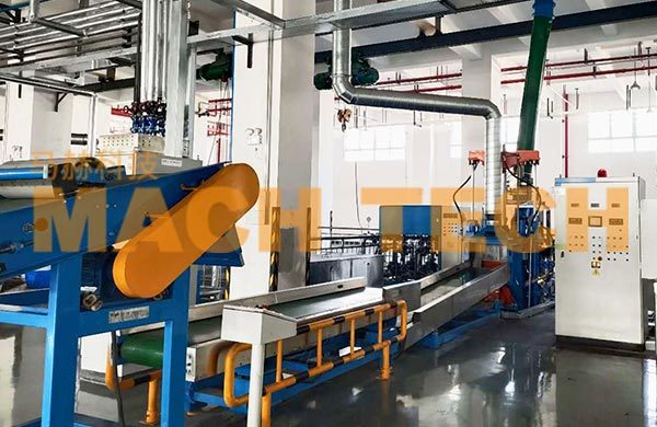
3. Rubber material conveying and weighing system
The rubber material conveying and weighing system mainly consists of a rubber block elevator, rubber sheet cutting machine, rubber sheet guiding machine, rubber material scale, and rubber material feeding conveyor belt.
(1) The rubber sheet guiding machine is responsible for pulling the rubber sheet apart. The rubber sheet cutting machine pulls the rubber sheet apart and cuts it into small pieces. The cutting knife is required to be uniform, and the speed of the conveyor belt is adjustable.
(2) The rubber material scale weighs the rubber material and sends the weighed rubber material to the feeding conveyor belt. The technical indicators of the rubber material scale are as follows: ① Weighing capacity; ② Weighing accuracy (weighing capacity × 0.10%); ③ Range graduation.
(3) The working length of the rubber material feeding conveyor belt is about 0.5m longer than the rubber material scale to ensure that all the prepared rubber material enters the feeding preparation section. The rubber material feeding conveyor belt consists of an electric roller, reducer, worm gear driven thin seamless belt, stainless steel guard plate, etc., and is controlled by a photoelectric switch to stop, feed, and feed material. The speed of the conveyor belt is adjustable.

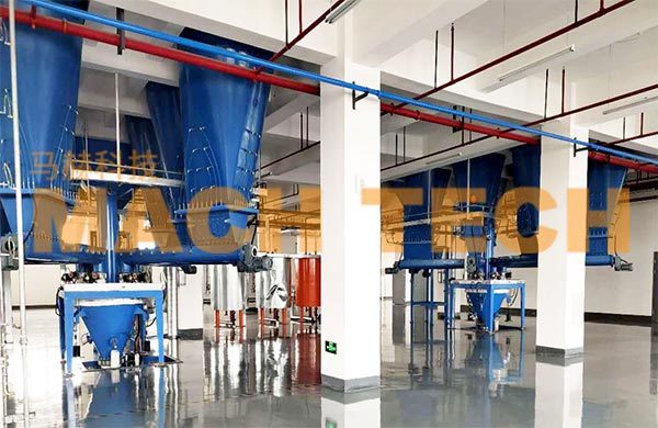
4. Dust removal, purification, and recovery system
A dust collector is installed at the unpacking port of each carbon black storage tank, and a set of negative pressure dust removal system is used for dust and gas separation and purification.
The carbon black input into the internal mixer will produce carbon black dust, and the input chemical raw materials will also produce dust; the oil-containing components in the formula rubber will be atomized at high temperatures in the mixing chamber. Therefore, the dusty gas discharged from the internal mixer feeding port has the characteristics of fineness, oil mist, adhesion, static electricity, and difficulty in ash removal after adsorption, and explosiveness. These factors should be fully considered in the design of the dust collector.
The internal mixer feeding device is equipped with a dust collector, which is processed by an independent dust removal and separation system. The dust from each batch of formula feeding is separated and collected, and immediately sent back to the next carbon black scale by an online return conveyor. Dust removal efficiency >99.95%, purified emission of particulate matter ≤12mg/m 3 Meeting national environmental protection requirements.

The above four systems constitute Auxiliary equipment Hardware components. Next time, I will explain the core of the auxiliary machine - the entire rubber refining control system...
Tags:
Beijing Mach Tiancheng Technology Co., Ltd.
Address: 12th Floor, Building B, Yu Hui Building, No. 73 Fucheng Road, Haidian District, Beijing
Telephone:86 010-88152355
Fax: 010-88133042
Email:xiayanqiu@machtech.com.cn